John's video also says "What's your problem":
http://www.youtube.com/watch?v=fps0OR1eF_s
It would be extemely interesting to see that cutter up close.
Phil:)
Cutting Tool Generatin -- new name
Re: tutorial doesn't match latest release?
Last edited by philbur on Wed Aug 17, 2011 11:59 pm, edited 1 time in total.
Re: tutorial doesn't match latest release?
Hi Art:
I had a second attempt. This time I cut the flats manually and then just ran the program for the volute with safe Z's inserted for each pass.
I thin the graphical presentation of the cutter thickness in the volute profile needs to be the diagonal thickness of the cutter. My second attempt was still to thick to sallow the cutter to rotate without rising some way out of the tooth profile as the diagonal passed over the tooth flanks.
The final Z height when cutting the involute seems to be way high. I had to run it again with Z0 2mm lower than the top of the stock. This may have something to do with me doing the flats manually and getting resetting of Z0 wrong, but I don't think so. The low side flash came of 2 passes earlier than the high side. Looking at the code as the end mill passes the cutter tip on the last pass the end mill should at least have a Z value that is half the stock diameter plus half the tool thickness and it is not.
Cutting the involute by progressively lower Z passes (with the same small DOC as the flats) seems to result in deflection of the cutter on the last pass. If the end mill came in from the side the risk of deflection would be greatly reduced and the need for constantly varying the Z height as it follows the involute profile would be unnecessary.
Phil:)
PS: I think a better graphical presentation of the cutter tip would be your diagram 3, where the circle diameter would be equal to the involute width at the cutter tip location (at the root).
Last edited by philbur on Sat Aug 20, 2011 1:26 am, edited 1 time in total.
Re: tutorial doesn't match latest release?
Hi Art:
How does one know the correct total depth of cut when using the cutter to produce a gear.
Also the root profile on the cutter will have zero clearance, not sure how much of a problem this may be. Using a slitting saw to pre-cut the slots to depth would help.
Phil:
How does one know the correct total depth of cut when using the cutter to produce a gear.
Also the root profile on the cutter will have zero clearance, not sure how much of a problem this may be. Using a slitting saw to pre-cut the slots to depth would help.
Phil:
Last edited by philbur on Sat Aug 20, 2011 3:08 am, edited 1 time in total.
Re: tutorial doesn't match latest release?
Hi Art:
Trouble with grinding the relief angle on the end is it has to be reversed either side of the axis of rotation.
Seems the maximum theoretical diagonal tip thickness for all spur gears is approximately 23%. Anything thicker is wider than the involute at that point.
The reason I ask about the depth of cut is that the cutter doesn't fit to the full depth of my reference gear. So the cutter used to produce my reference gear must have had a different full depth of cut, if you see what I mean.
Phil:)
PS: All the commercially produced gears I have to hand have a much more rounded root. See post 12 first photo.
Last edited by philbur on Sat Aug 20, 2011 4:50 am, edited 1 time in total.
Re: tutorial doesn't match latest release?
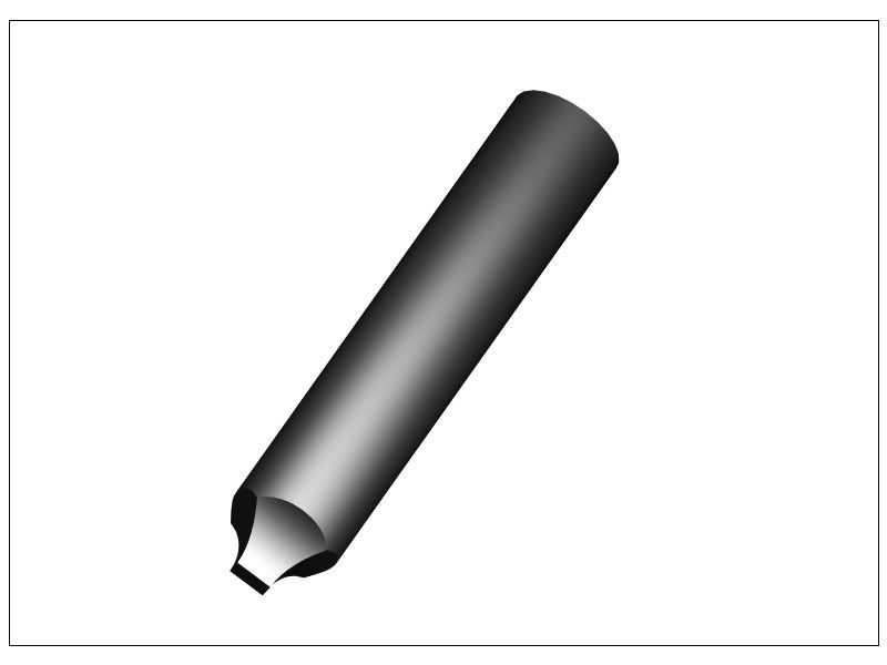
Here's a cutter ready for use. 5mm diameter - 1.5 module - 25 teeth, hardened and tempered.
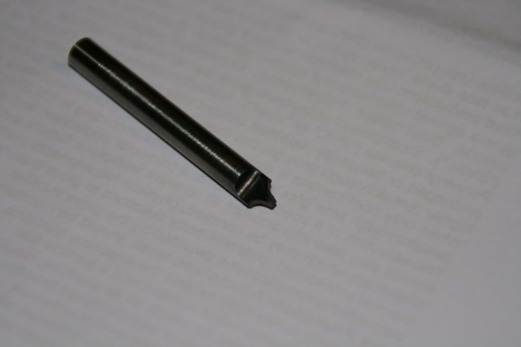
Phil:)
Phil:)
Last edited by philbur on Sun Aug 21, 2011 10:20 am, edited 1 time in total.
Re: tutorial doesn't match latest release?
Art:
Oops, possibly my mistake on the Z height. Just discovered tonight that I had make the cutter from 6mm stock, but the code was for 5mm stock.
Anyway I carried on with cutting the gear, just to confirm how the cutter would work. It didn't. The brass blank ate the cutter, so I rechecked the hardness on the tip with a file. Seemed pretty good so I checked further up the cutter with a scriber. It was somewhat soft. I need to take more care with the heat treatment. I didn't expect the brass to be such a challenge, although it is of unknown origin.
Anyway I'll redo it all all tomorrow.
Phil:)
ArtF wrote:
Still too high eh? Thats amazing, I told it to go to 1.6 times the depth just in case.
Ill revisit that math to see where I dicked up..
Art
Last edited by philbur on Mon Aug 22, 2011 10:51 pm, edited 1 time in total.
Re: tutorial doesn't match latest release?
To improve cutter strength how easy would this geometry be to produce code for. Its kind of a first step to a conical cutter but keep two cutting edges.
Instead of the cutter having two flat faces (with a thickness of less than 1mm) give the cutter two curves faces by profiling instead of facing the thickness, if you see what I mean. Or maybe it makes the maths for the involute to complicated. The input would be a diagonal width (Edit: of the none cutting edges) at the tip as a % of the root width (always less than 100%).
Phil:)
Last edited by philbur on Tue Aug 23, 2011 10:31 am, edited 1 time in total.
Re: Cutting Tool Generatin -- new name
Art:
So the only issue might be finding a company that will provide single lip engraving cutters with a 40 degree included angle? I'm sure there are companies out there who will make engraving cutters to order.
Alternatively I don't think most people care what standard pressure angles are use commercially. So if a 30 degree cutter can produce matching gears with a 15 degree pressure angle then most HSM'ers would be satisfied with using a stardard off the shelf cutter.
Phil:)
Edit: This opens up many possibilities with respect to the use of home made multi-tipped rotary cutters with a simple rack profile produced on a manual lathe/mill. Then you use it to make multiple passes, indexing the blank gear a fraction of a tooth on each pass, moving the rack profile cutter the corresponding fraction. Even I could write the code for that. Looks like I've got my own development project. Oops again! I already have the home made cutters, previously use for manual gear making using a different but not dissimilar process.
Last edited by philbur on Wed Aug 24, 2011 11:50 pm, edited 1 time in total.
Re: Cutting Tool Generatin -- new name
But a small diameter end-mill rotates at much higher rpm (say at least 10 and maybe 50 times) and has more than one cutting edge (say 2 flutes). So the number of facets per minute with and end-mill is order of magnitude 20 to 100 times that of a fly cutter.
Phil:)
PS: The flycutter does cut both faces at the same time. so 10 to 50?
PPS: Maybe not so simple, the fycutter is much stronger so DOC can be higher??
Phil:)
PS: The flycutter does cut both faces at the same time. so 10 to 50?
PPS: Maybe not so simple, the fycutter is much stronger so DOC can be higher??
Last edited by philbur on Sun Sep 25, 2011 5:29 am, edited 1 time in total.
Who is online
Users browsing this forum: No registered users and 17 guests