Art, it would be likely helpful to explain what I am doing and to show a couple of images.
Originally, I began by fabricating a heavy duty rotisserie that would support a whole pig and that includes 12 to 14 hours of non-stop turning-time over a fire. The motor is a Dayton (AC/DC) gear reduction motor (RPM 6.7, torque 162 in/lbs). The large wheel is a fly wheel from a 1985 Chev, 350 cu in engine, and the pinion gear on the Dayton motor is one that was originally designed to fit a starter motor and turn the engine?s fly wheel when starting the engine. This has worked quite well.
Next I decided to make the rotisserie device a ?double duty? contraption by turning it into a welding positioner that would slowly rotate a round part while I am welding (TIG, MIG, Spool, or Stick). I reasoned that if the rotisserie would easily support a hog, then it would surely support, say, a 4? piece of thin-wall-tubing that?s no longer than 12 inches.
The problem with which I?m faced is, the pinion and wheel are metal thus arcing between the gear?s teeth would likely occur when welding. Additionally, since the bearings are also metal, this too would create an electrical potential for arcing and welding together. Too, the motor needs to be isolated from the electrical welding circuit.
I needed a way to isolate and eliminate all electrical potentials so I decided to isolate the motor by using a Delrin pinion gear, as well as a plate of phenolic material between the motor?s metal base and the positioner with further isolation via phenolic spacers through the holes where the bolts secure the reduction motor. Additionally, I have chosen to remove the bearings (x2) and replace the bearings with Delrin bushings. Placing electrical brushes in close proximity to the part being secured in the chuck, I believe this will significantly reduce electrical potentials throughout the positioner?s frame.
Fabricating a new fly-wheel to match the pinion is not an option. I think the fly-wheel has somewhere around 134 teeth. Since the motor turns soooo slowly, and the fact that the weight of the tubing being welded is so slight, I will get quite a few miles of service from the Delrin gear.
In passing, I used gear-pitch gages (20 and 14.5 PA) to *initially* determine the PA and DP followed by careful measurements and math to corroborate the determined PA and DP.
Since the pinion gear is sintered, I assume the gear is proprietary and not a standard gear.
I am including a frontal view of the original pinion gear and an image of the rotisserie/positioner. One can easily see that *form* of the original gear is significantly different than the one I fabricated.
Finally, the Delrin gear seems to nicely articulate with the ?wheel? so I am in hopes this attempt will work. The proof is in the pudding.
Harold
Problem Encountered; need advise
Re: Problem Encountered; need advise
- Attachments
-
-
Last edited by Hwingo on Mon May 18, 2015 6:42 am, edited 1 time in total.

Re: Problem Encountered; need advise
HI Harold:
Yeah, I think youll be fine. Definitely a special gear, looks like a 30PA with a profile shift of -.5
But I think your fine.. that type of application should be fine with that gear. Congrats..
Art
Yeah, I think youll be fine. Definitely a special gear, looks like a 30PA with a profile shift of -.5
But I think your fine.. that type of application should be fine with that gear. Congrats..
Art
Re: Problem Encountered; need advise
MmmmMmMm!
I used to cook 150-200 lb hogs on a spit at 300-350 f for 10 hrs or so, but it was too much work and tension. There were just too many things that could go wrong. The pig would start falling apart before it was done, the hams and loins would start to dry before the shoulders were done, the fire had to be perfect -- lots of radiation but not too hot. The presentation was kind of ugly. Never had a bad fire, but there was always a charged hose right there.
Over the years the spit and pit have gone away, and the process has become a BBQ cook at 215 f for 15+ hrs in a converted oil tank. The fire is indirect and can be controlled easily, the pig isn't moving and so doesn't lose its juice, the only bad thing is the skin is inedible -- like a giant lobster shell. The hams and loins are tender and exploding with juice, and the shoulders are nicely rendered. Presentation is perfect, and the bones come out without tools. I get smoke ring 2" deep.
For smaller pigs -- <100 lb, the rotisserie roasting works great. I have a chain drive between the shaft and the speed reducer, and I drive the speed reducer with a belt drive from a tiny fractional hp motor. The pig turns at about 1 rpm.
Re: Problem Encountered; need advise
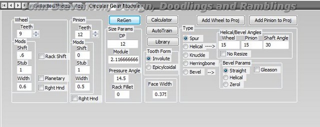
Will this do you Harold ?
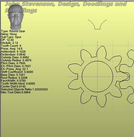
Ticks all your boxes and looks like the original.
You need a shift of 0.6 and 0.6 on the width.
Ticks all your boxes and looks like the original.
You need a shift of 0.6 and 0.6 on the width.
John S.
Nottingham, England
Nottingham, England
Re: Problem Encountered; need advise
Hi John. Thanks for replying. Yep, that looks like the one I was originally trying to duplicate. How did you know to do that?
Harold
Harold
Re: Problem Encountered; need advise
At this juncture I think it?s prudent to aggressively examine cuts made using Gearotic and critically scrutinize defects and/or deficiencies that are visually present in image-results posted earlier.
Aside from obvious morphological differences between the original gear and the one I produced, I can see at least one deficiency or omissions in the gear I fabricated. I would prefer to first establish *cause* for what I am seeing followed by a means of correcting the issue. Later, either on-line or via PM, I can speak with John S. regarding tooth form. Perhaps it would be beneficial to all that the issue of tooth form (morphology) be discussed on-line as there may be others to benefit from such discussion.
Because I am a beginner, I can see only one thing that quickly ?jumps out? whereas you, the experienced, will see additional things that are not obvious to me. I will begin with that which is obvious to me. I will include a screen shot and several additional images that may be of benefit.
I will need to make a second post, immediately after this post in order that I can include the last diagram and an account of the defect that I found.
Thanks,
Harold
- Attachments
-
-
-
-
Re: Problem Encountered; need advise
Take a look at the diagram included with this post. When viewing the actual image of the fabricated gear (see first image of previous post), I have identified ?ledging? with each tooth. The diagram alludes to ledges. Why has this happened and what must I do to correct this issue?
Harold
Harold
- Attachments
-
Re: Problem Encountered; need advise
Hi Harold:
The root ledging is because the tool cannot fit in that spot to do the undercut fillet. A Ball end mill may do a better job as it wouldnt leave as
sharp a contrasted edge. Cutting low tooth count gears is always a challenge due to undercuts , most gear makers recomment no fewer than 12 teeth for that reason, OR , as John pointed out, they give a profile shift to eliinate the undercut, no ledge then exists.
If you look critically at the 4th axis screen straight inwards, and watcht he tool move, youll see gettign that small rounded fillet
without a ball mill woudl be very difficult.. if not impossible for most gears, so the solution is to increase tooth count, add a profile shift,
( or run a round file on each tooth post production. ).
On original look at your gears I was of the opinion they were too thin...but Im revising that as it looks more like just a low tooth count, with
low pressure angle. 14.5 is not a good angle for low tooth counts, it accentuates the undercut, makes the tooth weaker and harder to make,
as you see by looking at Johns profile shifted tooth form, same tooth count, but much better root, with much higher strength in each tooth.
Art
Art
Re: Problem Encountered; need advise
Good Morning All,
So there seems to be at least one softly suggested message ?.. ?Gear fabrication is not strictly immutable? suggesting there may be a wee bit of ?wiggle-room? in either direction. I suppose this is where the learning curve begins to take form. Since I am a beginner, the natural progression is to ask, ?How does one begin learning how and when to modify shift? in order to make a stronger, working gear??
Is this to say that as long as you maintain the same PA and DP, shifting can be used to change the physical form of a gear and it will mesh quite well with the wheel providing long service?
Harold
Re: Problem Encountered; need advise
Hi Harold:
Well said. Tolerances derive from purpose. Any gear is only as good as its match to its purpose.
Profile Shift:
Consider two gears, a wheel and its pinion. If designed with zero shift, they have equal strength to
their teeth , no matter how many teeth each has except in the case of undercut. Their strength is a
function of their width, and the roots they have, its usually recommended to have no fewer than 12 teeth
generally .. but very generally. Its obvious that this cant be followed much of the time. When undercut
is in a gear, that gears teeth are weakened. Sometimes, depending on purpose, this may not matter.
Higher pressure angles can help remove undercut, but only to a point. After that..
A profile shift can remove that undercut ( or alleviate it) and add strength. This will change the mesh,
BUT, this too is fixable by shifting the other gears profile as well in the opposite direction, the mesh is then
correct.
There are limits of course, and they vary from gear pair to gear pair. To understand a profile shift, look at
the noncircular gear page. Its gears are created by rolling a rack around the blank of the gear. A "Profile Shift"
is simply shifting the rack outwards a set amount. On that screen is a rack tooth picture where the head normally is,
as you enter a shift, watch the pitch line on that rack tooth move. Tooth the gear to see the effect. As you shift outwards
the gears tooth gets less rack, so the root trochoids, if there are any, are much more shallow. Stronger teeth result.
BUT, since you moved the rack out for one, you must move it in on the mating gear to keep the pitchline respected.
As to how mobile the tolerances are and how worried you should be as to tolerance, that too is more a function
of purpose than gear. Look at some of the decorative gears you see on the web, many have triangular teeth with no
regard for pitchline. They function fine. Their purpose is not to drive any load, if they did a user of them would soon find
triangle teeth are natural vibrators, they cause the two gears to vibrate in velocity ( a first derivative vibration), that would
wear them out in short order. But as decorative gears, they are fine. Purpose trumps specification. For most things anyone here
would build a tolerance is allowed of quite a bit before trouble will be seen. If making a transmission gear, you want to be very accurate
indeed, if making a gear for a lathes change gears, you want close, but a bit of backlash isnt going to hurt you.
Creating backlash with tooth width respects the pitchline, that gear will be slightly weaker in tooth from being a bit narrower,
but will wear very well. At most its pressure angle may be slightly affected. A profile shift moves the pitchline to a new position, but fully respects it so long as the other gear is shifted in the opposing direction. ( Your gear looks shifted, so the wheel is probably already shifted.. )
but theres a lot of wiggle room in all this. In the end the application is so widely varied, thats its near impossible at any point to say
"this will work" or "this wont work" in any general sense. Except in demanding requirments I suspect most do as I do, intuitively look
at a requirment and decided if your being picky enough...or too picky... Its a rare gearhead who hasnt had the experience of making gears
too weak, or too strong for the thing they were building or fixing. Wisdom always comes at a price. :)
Art
Re: Problem Encountered; need advise
Good Morning Art,
Within the body of this Thread, referencing reply #11, I included an image of the original gear which clearly shows its physical form in frontal view.
Following John?s lead regarding shift thus subsequence form (post #14), I have *attempted* to take careful measurements of the original gear, e.g., width at root of teeth, space between two teeth at the roots, and the tiny thin edge that?s present on the OD of the teeth. Though my illustration does not accurately depict the original gear?s tooth-form, measurements are as close as I can get. Refer to illustration.
Is there a way that I can ?come close? to accurately measuring those areas depicted in John?s submission (post #14) with those measurements of the original gear so I can compare the two?
I can only assume that if the spaces between teeth, in John?s suggestion, are less than the space between the original gear then John?s gear will likely not work. For that matter, if the widths of teeth in John?s proposal are greater than the widths of teeth in the original gear, this too would suggest his gear would not articulate with my big wheel. Are these statements correct?
Lastly, is there a way to alter space distance, as well as tooth width so as to make John?s proposal workable? The reason I ask is, it would be nice to replicate form of the original gear as closely as possible. John?s proposal certainly comes very close if going by ?looks?.
Harold
- Attachments
-
Re: Problem Encountered; need advise
Hi Harold:
As you shift a gear positive, the spaces shrink between the teeth, the theory being the spaces on the other will be enlarged.
What you need is the width at the pitch line on the other gear, no other measurement is real important. If the width on the mating gears pitchline is X, then if yours is <=X your gear will work. If you have the capability to shift the center distance then you wont have any trouble no matter what you do, if you profile shift your gear outwards by .6 as John did, that implies only that you need to shift the center away from the original mate by the same shift if you dont intend to recut that one.
If it were me, Id make the one John suggested with .6 profile shift ( since the DP hasnt changed, it will mesh fine ), and Id slightly shift the new gear away form the original
if I found it too tight. A profile shift is really just pushing the pitchline outwards, ( for a positive shift), so a slight increase in shaft distance will correct it just fine.
In all this , there is always more than one way to skin the cat, and the accuracy, specially in your rotiseri wont impact you much I dont think.
Art
Re: Problem Encountered; need advise
Harold:
I see I didnt quite answer what you asked..
Generally, (teeth +2)/Diameter = DP is close enough to work in most cases to determine what you need to make, often its hard to be sure, they may have shifted,
or they may have drawn a gear in cad with no relationship to the math that should be used, when making a mate to an unknown gear it'd be hard to tell
where to measure. If I were really unsure and wanted to be close, why not just print one ( Gearotic will print to exact size) , then paste and cut from cardboard.
Try out a paper one, costs nothing and then youll cut one sure that it will fit fine. Only dnager is paper cuts.. and the use of dangerous scissors.. :)
Art
Re: Problem Encountered; need advise
Good Morning to All,
Art, for ?starters?, just a few quick questions:
1. Is the term ?Profile Shift? a term which has meaning exclusive to this program or is Profile Shift common ?lingo? that?s well known throughout the industry? Stated differently, if an individual (such as me) uses the term ?Profile Shift? in the presence of *any* Tool & Die maker being familiar with gear fabrication, will they quickly understand the term ?Profile Shift??
2. When you speak of ?Pitch Line?, are you specifically referring to ?Pitch Circle Diameter??
I think I am getting closer to understanding how to use this program. I have learned that I can actually populate a field with a fractional value, e.g. DP 11.05 or shift .53 or .58. I am not bound to whole numbers. This does make a difference. In testing this I have learned that distance between teeth is altered and can be measured using the "measure function".
Harold
Re: Problem Encountered; need advise
Hi Harold:
Indeed anyone from a gear making industry would recognise the term "Profile Shift". When I refer to the pitch line I do
mean the pitch circle ( though in my world its not always a circle. :) ) Gears mesh on that pitch circle, right on its line,
which is why I refer to it as a pitchline. The area the pitch line is the addendum. Now given a gear blank, a shaper will
cut teeth into the blank to a depth where the shapers pitchline matches the gears pitchline. This will generate a zero shifted gear.
But if I only cut the shaper into the blank less than to where the pitchlines match, then the gear is said to have a positive profile
shift. (Meaning in english the profile of the tooth is shifted outwards by a set amount. This changes the shape of the tooth )
Use the calculator button as well Harold, it will show you what fractional DP migth best suit you for a given center distance.
Art
Who is online
Users browsing this forum: No registered users and 1 guest